Thursday, 22 August 2013

Santiago Calatrava: Milwaukee Art Museum USA 1994

Image1: Showing First half of floor plan depicting the more public spaces of the facility, with the main hallway opening up to a large curvaceous panoramic view , light is allowed to circulate the area. 

Image 2: Second half of the floor plan showing the more private areas of the facilities, being the more proximal parts of the structure( bathroom , cleaning spaces for example) shown through the proximity between spaces. This can be compared with those of the public spaces I previously talked about in image 1, where the large open spaces and the close spaces between each image clearly defines the differences between the private and public areas. The main entrance at the back of the facility could also be defined as public as it is open to the elements. 

Image 3: The circulation of the building can be described in terms of a linear format. The user enters the facility from the back end of the structure and then continues almost on a straight path through the structure to the main large gallery space that opens up to a large window. 

Image 4: Light is used to help direct the user throughout the space and help define the public and private spaces. The Private spaces are less exposed to natural light through large windows and so becomes private to semi private. The user is directed from the main entrance of the facility at the back of the structure to the main gallery space through the use of light. Light draws the user towards its viewers which is part of the human condition. Calatrava has used this technique to help define the difference between light and dark spaces and thus direct the user throughout the facility. 

Image 5: The public and private spaces are defined through the use of interchanging height of the ceiling. The more public space such as the main gallery hall is a triple height  making the space more public due to the users proximity top the ceiling line which is much more 'open' then in comparison to the more private areas which the ceiling line is closer to the users height. 

image 6: Second half of image 5 showing the more private areas of the facility. 

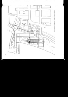
Image 7: Site plan 

image 8: Conceptual drawings and model showing part of the realisation process of  Calatrava's project.
Image 9: Conceptual drawings and model showing part of the realisation process of  Calatrava's project.

No comments:

Post a Comment